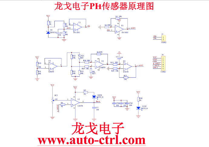
En effet un schéma vaut mieux qu’une longue explication, je te joins le schéma et la doc du 4502C pour info. Par contre pourrais tu me transmettre le tien?
La Documentation que j’ai réussi à récupérer
How to use a PH probe and sensor
If you worked with PH metering before you will know that PH values range from 0-14. Where PH 0 Will be very acidic, PH 7 will be neutral and PH 14 very alkaline. Water is near a PH 7 and this is usually around here that we will need to monitor PH of many things. A swimming pool, for example, should be slightly alkaline at 7.2, hydroponics systems around 6 (for optimum plant nutrition takeup) and aquaponics around 6.8.
I wrote this PH probe and sensor “how to” because it is not as straightforward as one would think (but quite easy when you understand the ins and outs) mostly because there is not a lot of information on this on the Internet, surely not detailed information.
We will first look at the ph probe module board and then the PH probe because both the PH probe and sensor have to be set correctly:
offset setting
limit setting
sketch to test the board analogue range
sketch for PH reading and calibration.
calibration of PH probe
PH probe usage
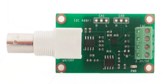
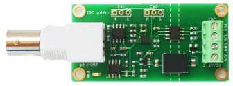
The ph probe module in this tutorial is available on our site here: PH probe module BNC conector
PH Probe Sensor Pinout TO – Temperature output DO – 3.3V Output (from ph limit pot) PO – PH analog output ==> Arduino A0 Gnd – Gnd for PH probe (can come from Arduino GND pin) ==> Arduino GND Gnd – Gnd for board (can also come from Arduino GND pin) ==> Arduino GND VCC – 5V DC (can come from Arduino 5V pin) ==> Arduino 5V pin POT 1 – Analog reading offset (Nearest to BNC connector) POT 2 – PH limit setting
PH probe module Offset and how to use it.
This board have the ability to supply a voltage output to the analogue board that will represent a PH value just like any other sensor that will connect to an analog pin. Ideally, we want a PH 0 represent 0v and a PH of 14 to represent 5V.
BUT there is a catch……, this board by default have PH 7 set to 0V (or near it, it differs from one PH probe to another, that is why we have to calibrate the probe as you will see later on), This means that the voltage will go into the minuses when reading acidic PH values and that cannot be read by the analog Arduino port. The offset pot is used to change this so that a PH 7 will read the expected 2.5V to the Arduino analog pin, the analog pin can read voltages between 0V and 5V hence the 2.5V that is halfway between 0V and 5V as a PH 7 is halfway between PH 0 and PH 14,
You will need to turn the offset potentiometer to get the right offset, The offset pot is the blue pot nearest to the BNC connector.
To set the offset is easy. First, you need to disconnect the probe from the circuit and short-circuit the inside of the BNC connector with the outside to simulate a neutral PH (PH7). I took a piece of wire, strip both sides, wrap the one side around the outside of the BNC connector and push the other side into the BNC hole. This short-circuit represents about a neutral PH reading of 7.
There are two ways you can do the adjustment.
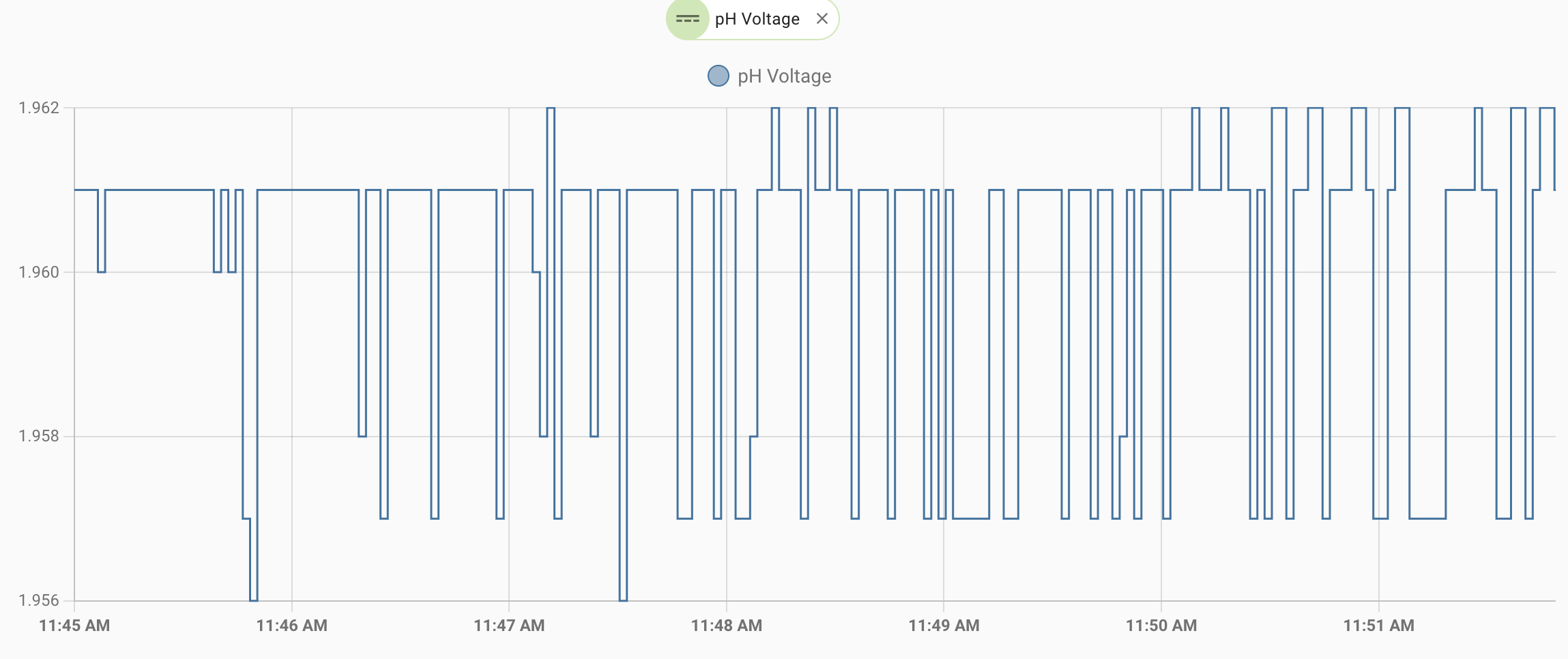
If you have a multimeter handy you can measure the value of the PO pin and adjust the offset potentiometer until PO measures 2.5V.
I prefer to just use the sketch below. Just download it to your Arduino as you will with any other sketch, open serial monitor and view the reading there. All this sketch does is to print the volts it receives from the analog pin and print it to the serial monitor. It of course first changes the digital value to volts to make it easier. Now simply turn the offset pot until it is exactly 2.5V. You can learn more about reading voltages and digital representation of volts here: https://www.arduino.cc/en/Tutorial/ReadAnalogVoltage